Intensifier Pump Detail
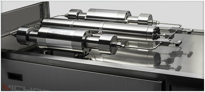
The advanced technology in the pump is found in the intensifier.

As mentioned briefly in the description of the water circuit, the intensifier pressurizes the filtered tap water to up to 94,000 psi. Intensifier pumps utilize the “intensification principle.”
Hydraulic oil is pressurized to a pressure of, say, 3,000 psi. The oil pushes against a piston biscuit. A plunger with a face area of 20 times less than the biscuit pushes against the water. Therefore, the 3,000-psi oil pressure is “intensified” twenty times, yielding up to 60,000-psi water pressure. The “intensification principle” varies the area component of the pressure equation to intensify, or increase, the pressure.
Pressure = Force /Area
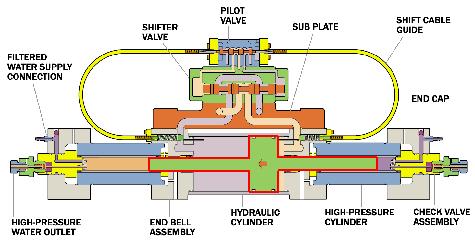
If Force = 20, Area = 20, then Pressure = 1. If we hold the Force constant and greatly reduce the Area, the Pressure will go UP. For example, reduce the Area from 20 down to 1, the Pressure now goes up from 1 to 20. In the sketch below, the small arrows denote the 3,000 psi of oil pressure pushing against a biscuit face that has 20 times more area than the face of the plunger. The intensification ratio, therefore, is 20:1.

In the illustration below, the biscuit and plungers are in the green section and outlined in red. The biscuit contains the small arrow suggesting movement to the left. The two water plungers extend from either side of the biscuit. High-pressure water is delivered out the left side while low-pressure water refills the right. At the end of travel, the biscuit/plunger assembly sequence is reversed.

Sophisticated check valves ensure the low pressure and high-pressure water is only allowed to travel one direction. The high-pressure cylinders and end caps that encase the plunger and biscuit assembly are specially designed to withstand the enormous force and the constant fatigue.
